Forward
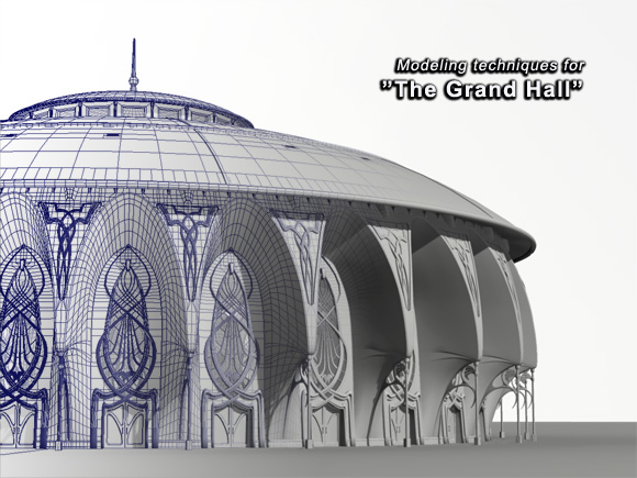
Hello everyone, the challenge for this piece was to model a building, but not to use bump or displacement maps for detailing.
This page outlines the progress of the design from start to finish.
As with most projects there was only limited time available for modeling, therefore choices have to be made in order to deliver the results on time.
It is always worth considering how your model could be textured, and allow that to guide the modeling process. There are various textures, such as bricks, that can be added as a bump map without the need to model them.
I hope you find this project breakdown interesting and useful.
|
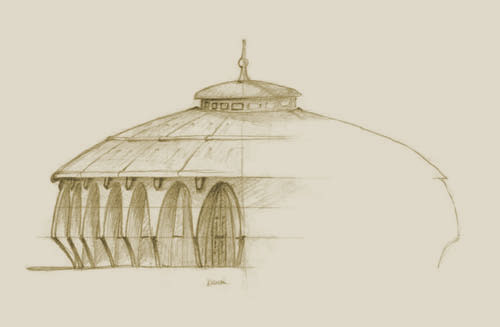
Step 1: Concept drawing The Brief was simple: model a building. This is, of course, an incredibley open brief, but one that allows for a lot of freedom and creativity I designed a large, airy building, maybe for use as a grand meeting hall, with Celtic and Art Nouveau influences. |
| |||
|
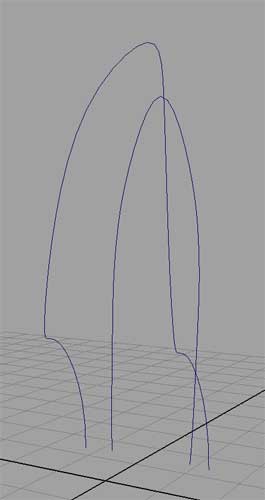
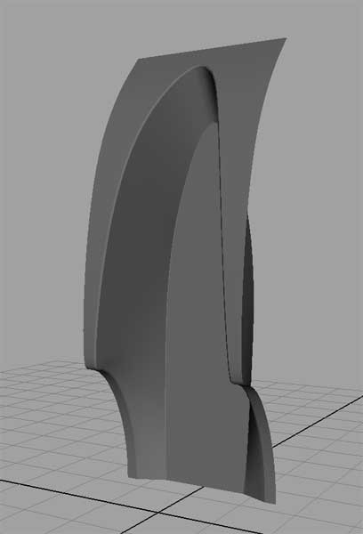
Step 2: Start the modeling The main feature is the curved indents, so using a surface loft from two curves, the curved wall was created. Personally I find polygons easier to work with when modeling and also texturing, therefore this NURBS surface was converted to polygons so that details can be modeled quickley. I'm only using the concept art for visual reference and not as an image plane, so there may need to be adjustments made to the final proportions. |
| |||||||||
|
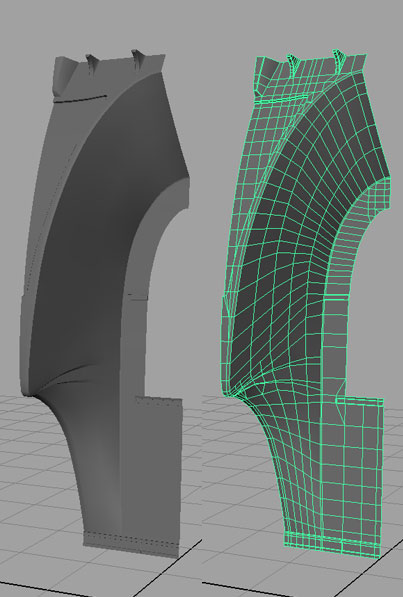
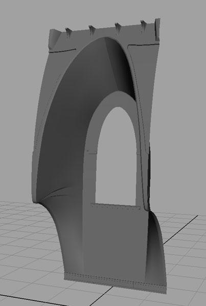
Step 3: Start detailing the wall There is only a need to model half of the wall section, which can be mirrored later. The window shape in these images is an early test. It is not in the style I'm after so I'll be coming back to change that later. For now I'll create some of the details such as the recess on the outter wall and the roof supports. Once the basic shape is complete, vertical edges can be added. This is because the wall will be bent into a circular shape later, and the bend needs to appear smooth |
| |||||||||
|
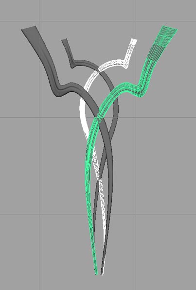
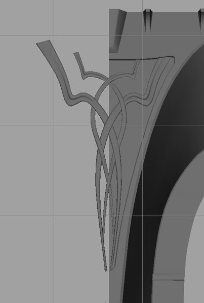
Step 4: Start detailing the frieze The outer piece was modeled by using the 'Create Polygon' tool, adding extra edges where control was needed to add the carving at the bend. This was converted to a sub-d surface (to get the nice curves). To make the inner piece, the outer piece was duplicated and scaled down. The shape was then modified. Once the look of both pieces is what you're after, duplicate and mirror them. Finally the celtic influence is added by weaving the pieces in and out. This is achieved simply my moving the vertices. A lattice deformer is used to bend the frieze to match the curve of the wall |
| |||||||||
|
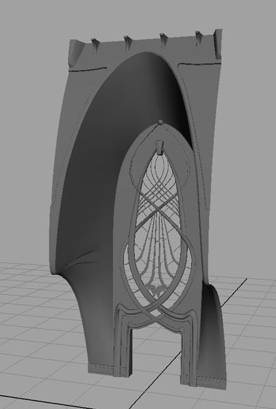
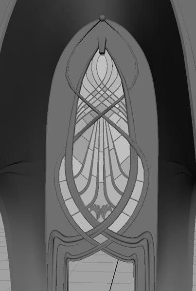
Step 5: Detailing the window The frieze is re-used to make the combined window and door frame, and the shape is tweaked. The style I'm after is like a flower or plant bud. As always you only need to model one half of the window frame so you can duplicate and mirror. Once the geometry has been mirrored you can weave the interleaving fronds together. The wall needs a cutout to match the window frame shape. The wall is then duplicated, mirrored, and combined to make one wall section. Remeber to check the normals along the join, and adjust them is necessary. Lots of curves and small joints in the window will help define the scale. Some of these are polygons, some are sub-d's Finally, add the panes of glass. Each pane is a separate polygon rotated at a slight angle. This will make the glass reflect light at slightly different angles, since the suns rays are almost parallel. This gives a more realistic 'aged' look, after all, this isn't a modern building it's a hand crafted work of art ;) |
| |||||||||
|
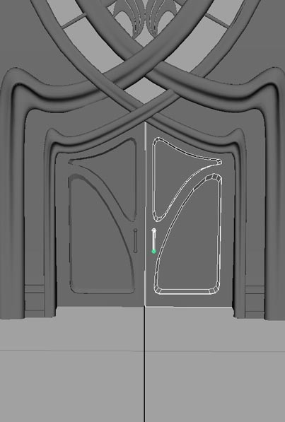
Step 6: Detailing the door The style this time is more Art Nouveau. As before, there is only a need to model one door, then duplicate and mirror it for the other door. A polygon cube was used for the door. The 'create poly' tool was used in the front viewport to draw the shapes for the indents. These shapes were extruded and beveled, then 'boolean difference' with the door polygon to make the indents. Remember to delete the objects history. While this method does not make for a very clean model, it is going to be fine for a detail which will be very small in the final image. It will be easy to clean up this low resolution geometry later if required. Items like the handles are very simple, low resolution models, but will help give a sense of scale. |
| ||||
|
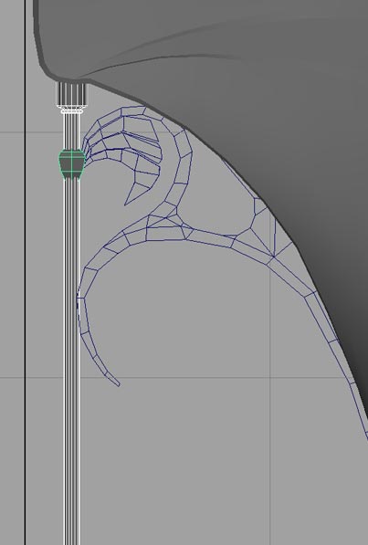
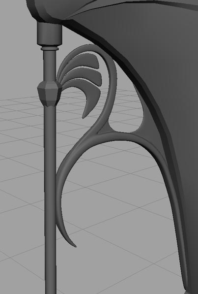
Step 7: The exterior ironwork Time for some more classic Art Nouveau styling by adding some curved ironwork to make archeways. I want the space between the curves to have a form of its own; to have the appearance of leaves. Sub-d's will be easy and fast to work with for this, making partial creases for the 'outside' edges The pillar is a simple extruded cylinder. Again it's quite low resolution as the final shot isn't intended to be a close up, and it will be quick to texture should that be required. |
| |||||||||
|
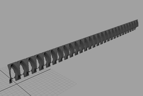
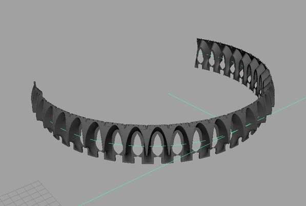
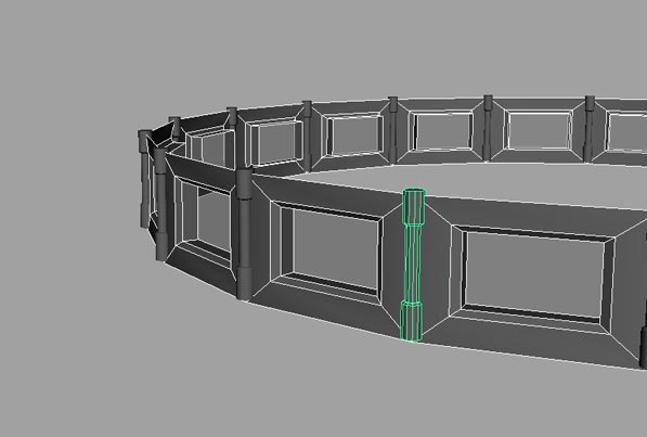
Step 8: The completed wall To make the building, we must first create a continuous wall. A single wall section was selected and duplicated the required number of times. Ideally we would layout all the UV's and assign a basic shader before duplicating, then the duplicates would all have correct UV layouts with no effort. I like to layout all objects with similar characteristics on one shader network, rather than one shader for each object. To avoid an obvious repeating texture, it would be best to assign a separate shader for the first duplicate, another new shader for the next duplicate - about 3 or 4 different shaders should be enough, and it will give you optoins when texturing. You can always revert to a single shader later if needed, rather than try to add shaders to a wall thats been duplicated and manipulated. Use SHIFT + d for the first duplicate, then move the duplicate to butt up to the first wall section. You can now use SHIFT + d multiple times to automatically create the remaining wall sections with the correct spacing. From my concept drawing I can see that I need 28 wall sections. Duplicate and combine the polygon objects. Note: Good use of layers will allow you to work without too much slow down in the viewport, as you'll have lots of polygons for glass, arches, frames and the frieze. I also found that it was easier to convert all objects to polygons before applying the bend, Maya seems to have an easier time of it this way. A bend deformer can be applied to the entire wall, adjusting the 'curvature' to create a circular wall (shown at about halfway in the picture). The final seam will be placed out of shot, so it doesn't have to be absolutely perfect. |
| |||||||||
|
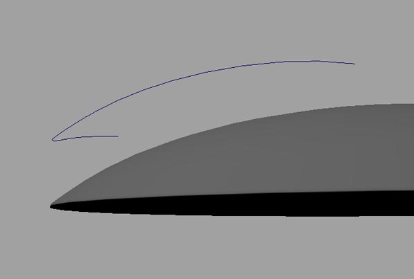
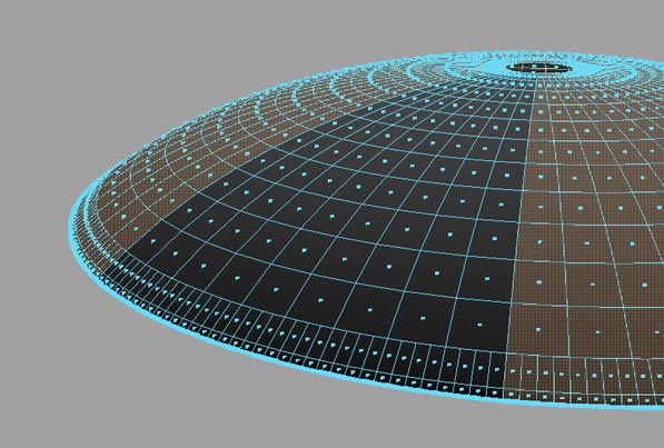
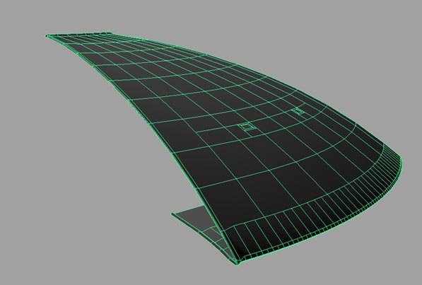
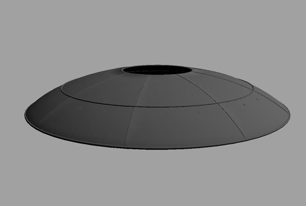
Step 9: The roof Time to get the roof modeled. A curve for the shape of the roof was created and revolved to make the roof surface. Since I want to model overlapping sections of roof, I have decided to convert the roof to polygons. You might want to snap a locator to the center of the roof for reference later, then everything except one segment can be removed. Using this method you can model one segment and then duplicate it to recreate the entire roof. Model a small lip running down the leading edge by selecting the edge, extruding it and tweaking its position. This needs to be repeated a few times in order to model the rounded shape of the lip. Two vent holes are modeled by cutting a face and extruding it to achieved the desired shape. Finally a small lip is modeled at the top where the roof dome will protrude. As in step 8 above, once the segment has been modeled, the UV's can be layed out so that all duplicates automatically have a UV layout. Duplicate in a similar way to step 8, but modify the rotation. This may need you to move the objects origin to the center of the roof's circle rather than the center of the segment. You can press INSERT and snap the origin (holding the V key) to the locator you created earlier, then press INSERT again to toggle back to normal mode. Since its likely to rain at some point, I have two gutters to catch the runoff. These are created using a nurbs torus, one positioned at the rim and one half way up the roof line. I guess there must be internal guttering channels for the water. |
| |||||||||||||||||||
|
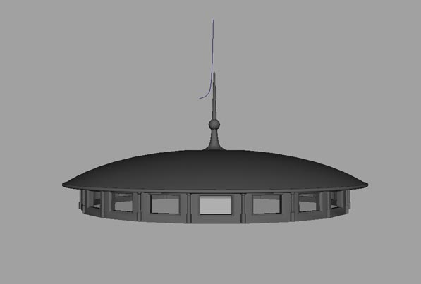
Step 10: The roof dome Since the dome is not very visibility in the final shot, the windows are created using a polygon cylinder. By selecting the faces and extruding it is possible to model the windows very quickley. Apply a semi-transparent material to the faces that make up the window panes. The pillars add an interesting visual feature that will catch the light, and are created from a polygon cylinder. The dome and spire are created separately by revolving two curves. A NURBS sphere (on the spire) and torus (for the guttering) make up the final details. When you put it all together, you get the completed roof. This should also be easy to texture. |
| ||||||||||||||
|
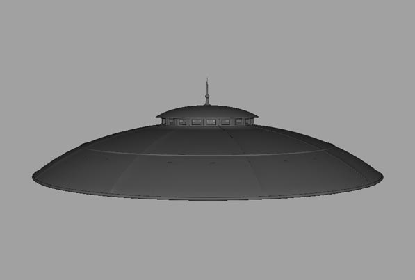
Step 11: Putting it all together I open the file with the wall (this has most of the detail and is a heavy scene), and import the roof object. Line them up manually and add a ground plane. The final proportions of the build are different to the concept art, but I like the new shape so there's no need to change it. The scene is now ready for lighting and rendering. Texturing will add a lot of extra detail that isn't practicle to model, such as stonework |
| ||||
|
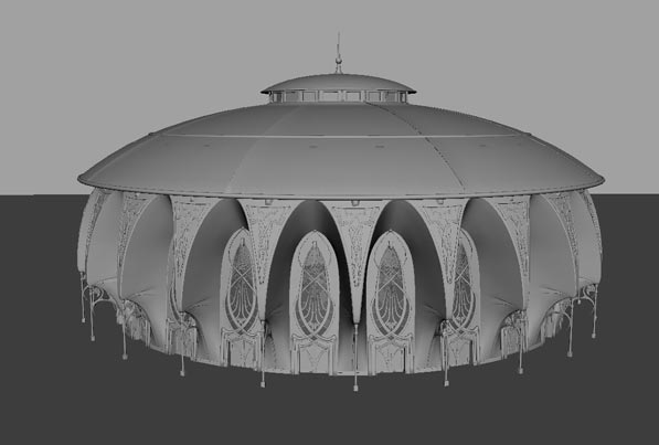
Step 12: The final shot By Creating a shot camera, you can position it, setup the view angle, and lock its translate/rotate values to prevent accidental moves. If you do move the camera by mistake, use the '[' to revert to the previous camera view. This way you can use the perspective view to move around your scene, but always have a camera set for your reference shot. The final concept was rendered using Mental Ray, with Global Illumination and Final Gather, with a main shadow casting 'sun' light. |
| |||||